Series
Source: 0.0053A
R1: 0.0053A
R2: 0.0053A
R2: 0.0053A
All of the currents through each resistor are the same.
Paralell
Source: 0.00729A
R1: 0.00549A
R2: 0.00119A
R3: 0.0061A
The sum of the currents through the resistors is equal to the current from the source.
Tuesday, 31 March 2015
Assignment #2
Source Voltage = 8.31v
R1 Voltage = 0.49v
R2 Voltage = 2.31v
R3 Voltage = 4.83v
Diode Voltage = 0.65v
R1 Voltage = 0.49v
R2 Voltage = 2.31v
R3 Voltage = 4.83v
Diode Voltage = 0.65v
Thursday, 26 March 2015
Robotics Assignment 1
Source voltage: 7.94V
Diode voltage: 0.77V
Resistor voltage: 4.94V
LED voltage: 2.06V
Sum of voltages = 7.77
The values in step 1 and step 3 are the same because voltage in series circuits add.
Diode voltage: 0.77V
Resistor voltage: 4.94V
LED voltage: 2.06V
Sum of voltages = 7.77
The values in step 1 and step 3 are the same because voltage in series circuits add.
Friday, 20 March 2015
Series vs Parallel Circuits
Series: In a series circuit, the components are connected one after another. This makes the current be the same across all components and the voltage across the circuit is the sum of the voltages across each component.
Advantages: Additional power sources can be easily added to gain more power.
Disadvantages: You are unable to control each component individually. Every component has to be powered even if you only want to use one of them.
If one of the components fails, all components after it will not be powered. This is commonly seen in Christmas lights.
Parallel: In a Parallel circuit, each of the components are separated from each of the others. This makes the voltage across each component be equal to the voltage across the circuit. The current across the circuit is the sum of the current across each component
Advantages: Components can be controlled individually.
If one component fails, all others will still work.
Disadvantages: Has a higher risk of fire.
Adding more power sources will not increase the voltage delivered.
Tuesday, 17 March 2015
Differences Between AC and DC
AC, or Alternating Current rapidly changes the direction in which the current is flowing. Sometimes the current is flowing forwards, and sometimes backwards. This changes many times a second. This was invented by Nikola Tesla
DC, or Direct Current only flows in one constant direction. This was invented by Thomas Edison
Alternating Current is what is delivered through the power outlets in our houses. It is more commonly used because it has better power transmission. Some electronics, however, require the use of Direct Current. One common example of this is our computers. The power supply in the computer converts the AC electricity from the wall into DC electricity that the computer components require.
Common Symbols
Transistors
Diodes

Integrated Circuits Resistor
Capacitors
Inductors
Switch
Wire
Source
Terminals
Fuses/Circuit Breaker
Diodes

Integrated Circuits Resistor
Capacitors
Inductors
Switch
Wire
Source
Fuses/Circuit Breaker
Thursday, 12 March 2015
Electric Components
Transistor: Transistors are used to control how much electricity is flowing through a circuit
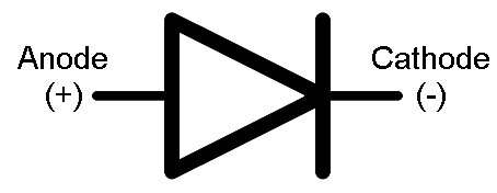
Diode: A diode restricts the flow of an electric current to one direction only. This direction is called the diode's forward direction.
Resistor: A resistor is used to control the flow of current. It can limit the amount going to a component to make sure it only received the amount of current that it can handle.
Capacitors: A capacitors main purpose is the storage of energy.

Inductor: An inductor is used to store current and then let it go with a continuous growth. It resists change in the amount of current flowing through it.
Diode: A diode restricts the flow of an electric current to one direction only. This direction is called the diode's forward direction.
Resistor: A resistor is used to control the flow of current. It can limit the amount going to a component to make sure it only received the amount of current that it can handle.
Capacitors: A capacitors main purpose is the storage of energy.
Inductor: An inductor is used to store current and then let it go with a continuous growth. It resists change in the amount of current flowing through it.
Definitions
Charge (Coulomb): a coulomb is a measure of how many electrons can be transported by a current of 1 amp in 1 second.
Electric Potential Difference(Volt): A measure of how much electric energy is lost between two points on a circuit
Current (Ampere): Current is the rate at which charge is moved in a circuit
Resistance (Ohm): Resistance measures the opposition to the flow of electricity through a conductor.
Power (Watts): Power is the rate at which work (joules) can be done.
Energy (Joules): A joule is the measure of the amount of energy it takes when a force of one newton is applied over a distance of one meter
Inductance (Henry): Inductance is the ability of a circuit or conductor to generate an electromotive force
Capacitance (Farad): Capacitance is the ability of an object to store electric charge.
Subscribe to:
Comments (Atom)